| “This site contains affiliate links for which OEMDTC may be compensated” |
2006-2009 MAZDA3 AND 2006-2009 MAZDA5 – A/C STOPS COOLING/REDUCED AIRFLOW DURING A LONG DRIVE IN HUMID TEMPERATURES
APPLICABLE MODEL(S)/VINS
2006 – 2009 Mazda3 vehicles (including Mazdaspeed3)
2006 – 2009 Mazda5 vehicles with VINs lower than JM1CR ****** 348679 (produced before November 1, 2008)
With the A/C on during an extended drive, the vent air volume decreases and/or the vents start to blow warm air.
This could be result of the evaporator freezing, and it is most likely to occur while driving for an extended time at steady highway speeds with the A/C on MAX in high humidity conditions.
When the freeze-up occurs, the following symptoms may be present:
- During freeze-up, the low pressure side pipe will have frost on it, giving the appearance it is frozen.
- Allowing the evaporator to unfreeze will temporarily address the concern.
NOTE: There are other conditions that can create similar symptoms, which include:
- During acceleration (throttle valve opening angle 50% or more). The duration is 5 seconds.
- When ECT (engine coolant temperature) is 113°C (235°F). The system repeatedly turns on and off every 20 seconds until the ECT is less than approximately 110°C (230°F).
- When ECT is 117°C (242°F) or more. The system will remain off until the ECT decreases to less than 114°C (237°F). These conditions signify the engine is running hot and could be on the verge of overheating.
- Electrical or mechanical concerns that could restrict vent air flow, causing irregular operation of the blower motor, and/or engagement of the A/C compressor.
The cause of the evaporator freeze-up is product variation of the evaporator temperature sensor and uneven airflow across the evaporator. To correct the sensor, a short harness with a built-in resistor will need to be installed in series with evaporator temperature sensor circuit. This cord will correct it by reducing the measured value 1°C (1.8°F). To correct the airflow, a cabin filter with a built-in diffuser will need to be installed in place of the current filter.
Customers having this concern should have their vehicle repaired using the following repair procedure.
REPAIR PROCEDURE
- Record the customer’s radio station presets.
- Disconnect the negative battery for at least one minute.
- Remove the side wall on the passenger side foot well.
- Remove the Passenger Juction Box.
NOTE: PJB module configuration does not need to be performed since the same module will be used.
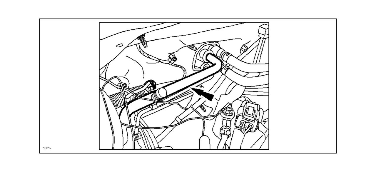
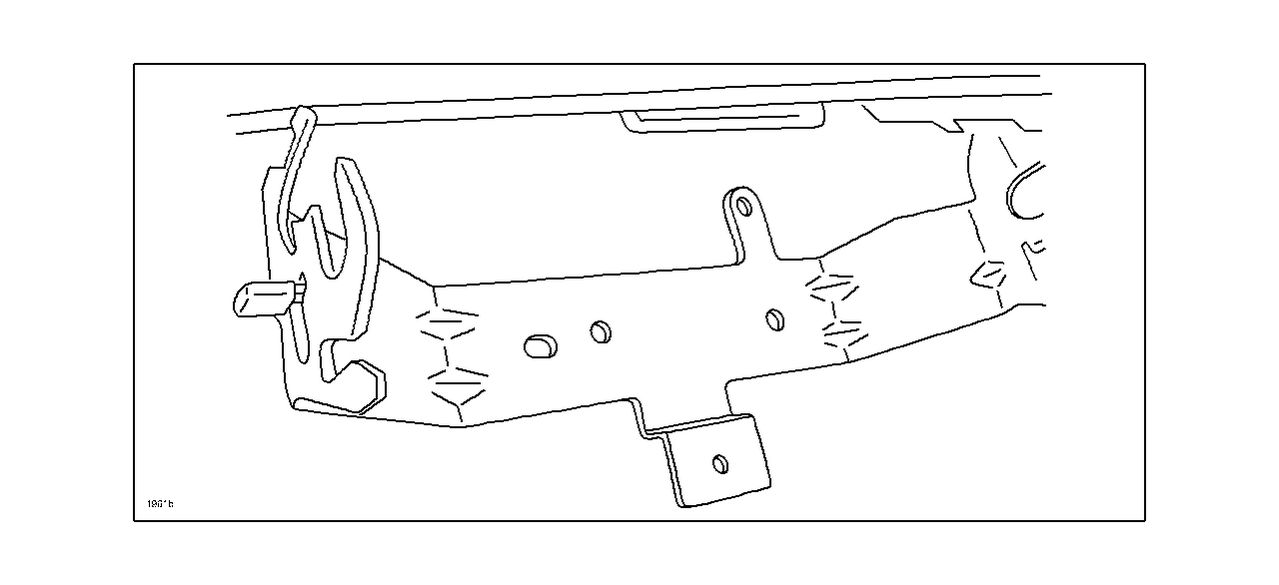
- Remove the metal bracket.
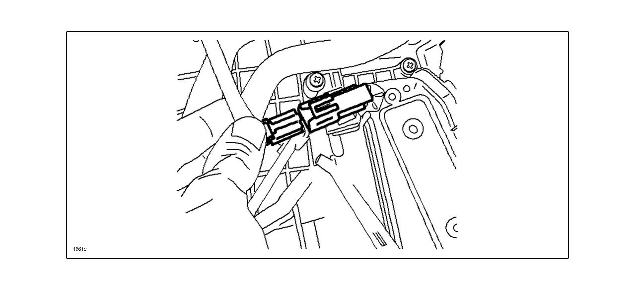
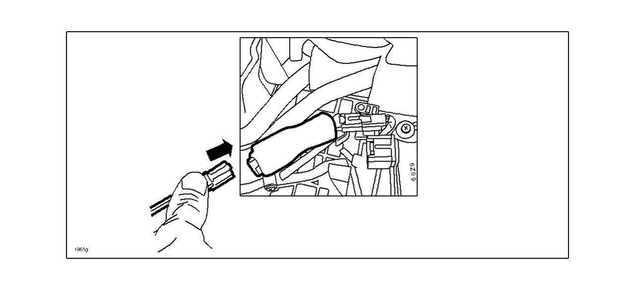
- Disconnect the connector from the evaporator temperature sensor connector.
- Disconnect the power MOSFET (if equipped with automatic climate control).
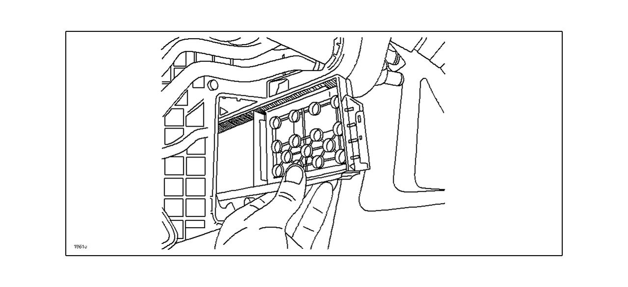
- Remove the evaporator access cover from the A/C unit.
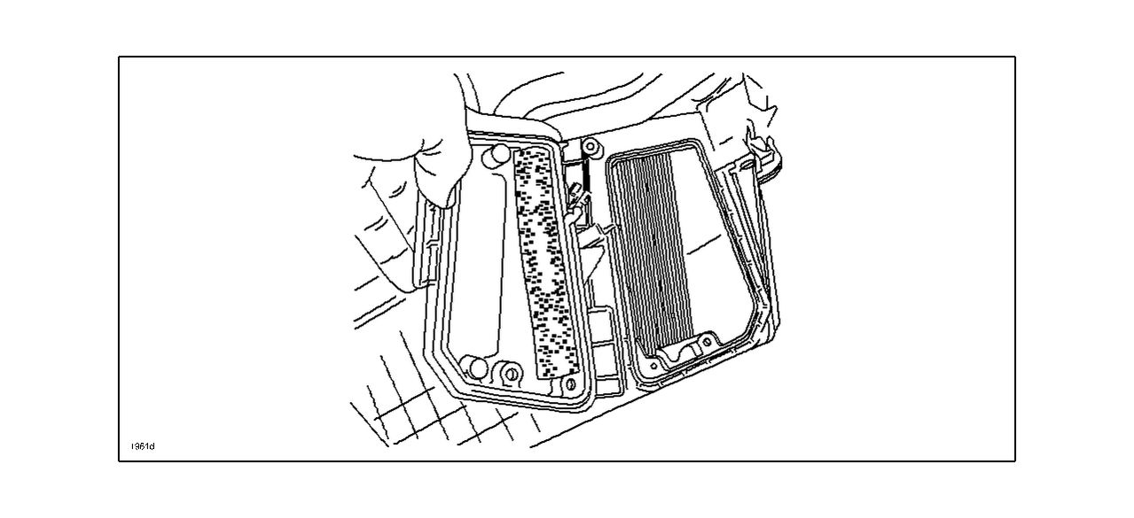
- Remove the upper and lower air filters from the A/C unit.
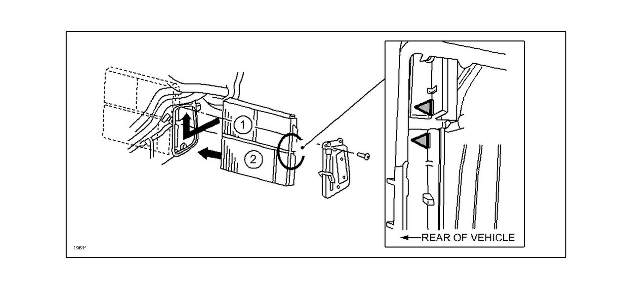
- Install the air filter with diffuser plate.
- Install the air filter.
NOTE: Make sure the arrows marked on the air filter are facing towards the rear of the vehicle.
- Install the evaporator access cover to the A/C unit.
- Install the short harness with resistor to the connector, then connect the evaporator temperature sensor connector to it.
- Reassemble in the reverse order of removal.
- Reconnect the negative battery cable.
- Enter the customer’s radio presets and set the clock.
PART(S) INFORMATION
| Part Number | Description | Qty. |
| BP8P-61-J6X |
Air Filter Set (with diffuser plate) | 1 |
| BPY1-61-545A | Short Harness (with resistor) | 1 |

