| “This site contains affiliate links for which OEMDTC may be compensated” |
2010-2015 CX-9 AWD – REPLACEMENT PROCEDURES FOR THE TRANSFER OIL SEALS (RIGHT SIDE)
APPLICABLE MODEL(S)/VINS
2010-2015 CX-9 equipped with AWD
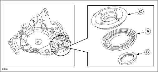
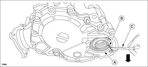
If replacement of the right side (RH) transfer oil seal (A), and transfer dust seal (B) are necessary, use the following REPAIR PROCEDURE to install the new oil seals.
NOTE: Deflector (C) may not be reused.
REPAIR PROCEDURE
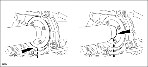
The transfer may leak different color fluids, red automatic transmission fluid (ATF) and tan/brown/black transfer gear oil. The transfer oil seal (A) prevents transfer gear oil leakage. It is important to note which color fluid is leaking to determine the most appropriate service.
NOTE:
- This repair procedure is to be performed through the RH wheel opening.
- It is not necessary to remove the transfer assembly from the vehicle.
- The transfer oil seal (A) and dust seal (B) are not a source of a red ATF leak.
- The transfer oil may appear black and have a pungent odor. Do not mistake this for contaminated fluid.
- Lift the vehicle. For additional information, refer to MS3 online or Workshop Manual (section 00-00).
- Is there a fluid leak from the RH side of the transfer?
- Yes – Proceed to Step 3.
- No – This does not apply. Refer to normal Workshop Manual diagnosis.
- Inspect the transfer vent located on top of the transfer. Is the transfer vent restricted (mud/debris)?
- Yes – Clear external restrictions from the transfer vent and proceed to step 25.
- No – Proceed to step 4.
- What is the color of the fluid leak?
- Tan/brown/black (transfer gear oil leak) – Proceed to Step 5.
- Red ATF leak – This does not apply. Red ATF leak indicates the transaxle seal is leaking and needs to be replaced. Refer to MS3 online or Workshop Manual (section 05-17).
- Remove the RH wheel.
- Remove the RH side cover.
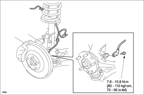
- Remove the RH front ABS wheel-speed sensor.
- Apply the brake to keep the half-shaft from rotating for the front wheel hub nut removal.
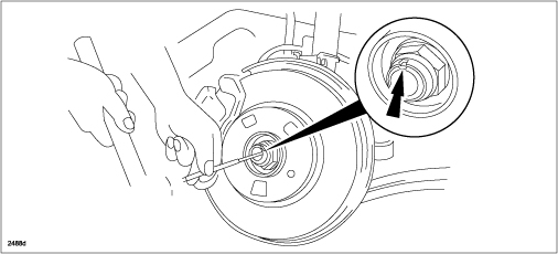
- Loosen the wheel hub nut so that the nut is flush with the end of the drive shaft.
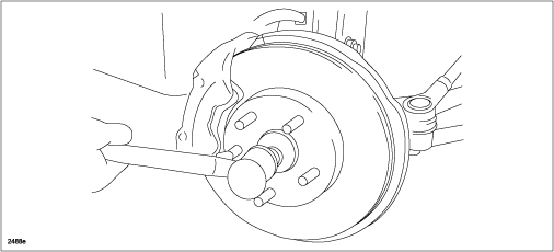
- Tap the hub nut with a copper or dead-blow hammer to loosen the drive shaft from the front wheel hub.
- Remove and discard the wheel hub nut.
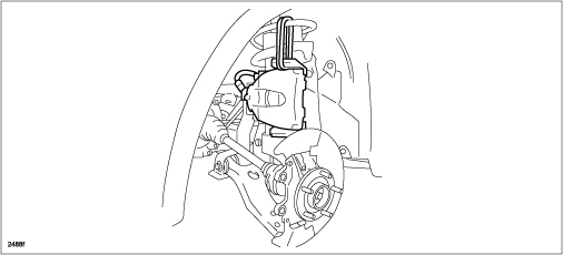
- Remove the brake caliper component from the steering knuckle and suspend it out of the way using a cable.
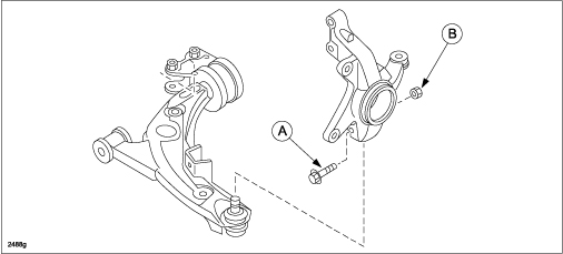
- Remove the front lower arm ball joint bolt (A) and nut (B). Then separate the lower control arm from the knuckle.
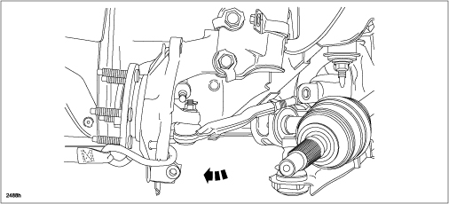
- Pull the knuckle outward, rotate it toward the rear of the vehicle, and secure it.
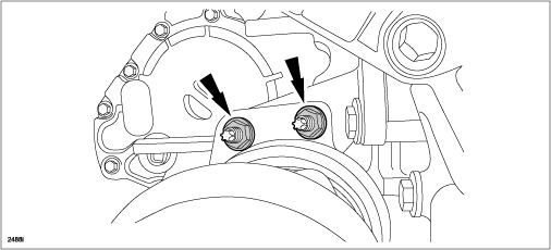
- Remove the two (2) RH drive shaft bolts and the drive shaft assembly.
CAUTION: The sharp edges of the drive shaft can slice or puncture the oil seals. Be careful when removing the drive shaft from the transaxle.
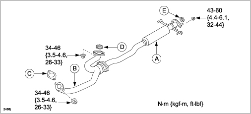
- Remove the exhaust middle pipe (A) and the front pipe (B) as an assembly. Discard (C), (D) and (E) exhaust gaskets.
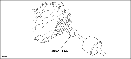
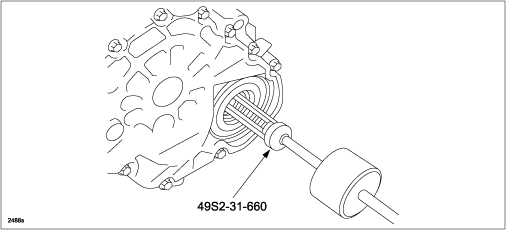
- Use Special Service Tool (SST) part number 49S2-31-660 or an Appropriate Seal Puller to remove the deflector.
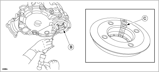
NOTE: Do not reuse the removed deflector (B). If the deflector is difficult to remove using SST 49S2-31-660 or an Appropriate Seal Puller, break the deflector by using a flat-blade screw driver for hammering (C).
- Use SST part number 49S2-31-660 or an Appropriate Seal Puller to remove the transfer dust seal.
- Remove the oil seal (A).
- Insert a tapping screw (B) into the groove of the oil seal.
- To remove the oil seal, pry the screw outward by using a fastener remover tool (C).
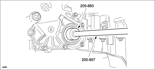
- Use SST part number 205-907 and part number 205-883 or an Appropriate Seal Installer to install the new transfer dust seal.
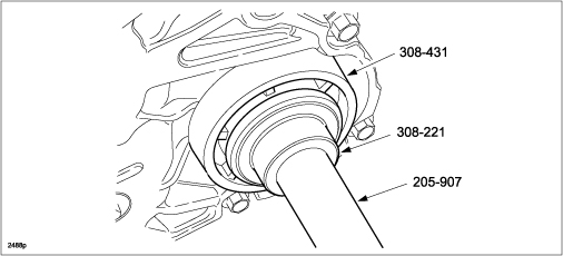
- Use SST part number 205-907, part number 308-221, and part number 308-431 or an Appropriate Seal Installer to install the new oil seal.
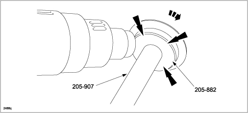
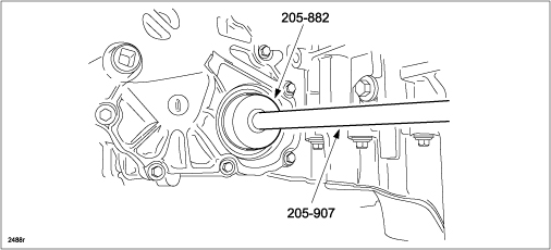
- Use SST part number 205-907 and part number 205-882 or an Appropriate Seal Installer, then install new deflector on SST. Heat the outer side surface of the deflector by heat gun at 250°C (482°F) for approximately 30 seconds.
- Use SST part number 205-907 and part number 205-882 or an Appropriate Seal Installer to install the new deflector to the case until it seats.
CAUTION: Use gloves when handling the deflector as it may be hot after Step 23.
- Install removed components in reverse order.
- Inspect transfer fluid level per MS3 online or Workshop Manual (section 03-16).
SPECIAL SERVICE TOOL (SST) INFORMATION
| Part Number | Description |
| 49S2-31-660 | Needle Bearing Puller |
| 205-882 | Transfer Dust Shield Installer |
| 205-883 | Seal Installer |
| 205-907 | Driver Handle |
| 308-221 | Seal Installer |
| 308-431 | Half-shaft oil seal installer |
PART(S) INFORMATION
| Part Number | Description | Qty. | Note |
| AW21-27-272 | Dust Cover | 1 | Deflector |
| AW21-27-398 | Oil Seal | 1 | Transfer gear oil seal RH |
AW21-27-514A | Oil-Idle Gear Seal | 1 | Transfer dust seal |
| LA01-33-042B | Nut | 1 | Wheel hub nut |
| CY01-40-305A | Exhaust Gasket | 1 | LH Catalyst gasket |
| CA01-40-581 | Seal Ring | 1 | RH Catalyst gasket |
| AJ17-40-305 | Exhaust Gasket | 1 | Middle pipe rear gasket |
