| “This site contains affiliate links for which OEMDTC may be compensated” |
MULTI-MODEL – DRIVER SEAT GRADUALLY MOVES DOWN BY ITSELF
APPLICABLE MODEL(S)/VINS
2014-2015 Mazda6 vehicles without power seats with VINs lower than JM1GJ******218764 (produced before Oct. 31, 2014)
2013-2015 CX-5 vehicles without power seats with VINs lower than JM3KE******548562 (produced before Oct. 31, 2014)
Vehicles (without power seats) may exhibit a driver seat that gradually moves down by itself.
This concern may be caused when a load, which is applied to the seat during braking, exceeds a certain level that could impact the retaining mechanism of the seat lifter causing the seat to gradually move downward.
To eliminate this concern, the play in the lift mechanism gears has been reduced.
REPAIR OUTLINE
NOTE: Ensure the customer is not bumping or touching the adjuster by mistake when entering or exiting the vehicle.
- Replace the driver seat lift unit with the newly established service parts kit according to the “SEAT LIFT UNIT (SERVICE PARTS KIT) REPLACEMENT PROCEDURE”.
NOTE: Replace the following parts (specified as “Replacement Parts” in the Workshop Manual) with new ones:
- Front seat side cover clip
- Recliner knob (with lever type recliner knob)
- Lifter knob
SEAT LIFT UNIT (SERVICE PARTS KIT) REPLACEMENT PROCEDURE:
- Remove the driver seat adjuster unit according to the instructions on MS3 online or the Workshop Manual.
- Disassemble the seat adjuster unit.
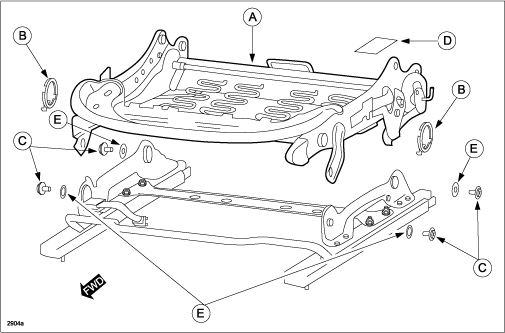
- Replace the subject parts (A – D) with the parts in the Service Parts kit.
- Re-install the driver seat adjuster unit according to the instructions on MS3 online or the Workshop Manual.
Service Parts kit includes:
NOTE: Be sure to save and re-use all washers (E). New washers are NOT included in the Service Parts kit.
REPAIR PROCEDURE
NOTE: Ensure the customer is not bumping or touching the adjuster by mistake when entering or exiting the vehicle.
- Remove the driver seat adjuster unit according to the instructions on MS3 online or the Workshop Manual section 09-13.
- To prepare the driver seat adjuster unit for disassembly, place the unit on a clean table or work bench.
DRIVER SEAT ADJUSTER UNIT DISASSEMBLY:
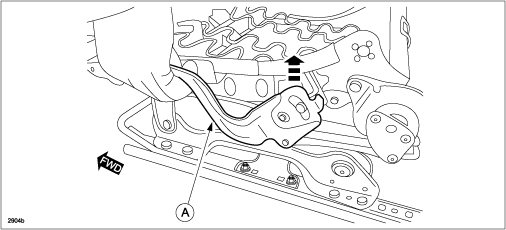
- Lift the seat lift unit to the highest position using the lift lever (A).
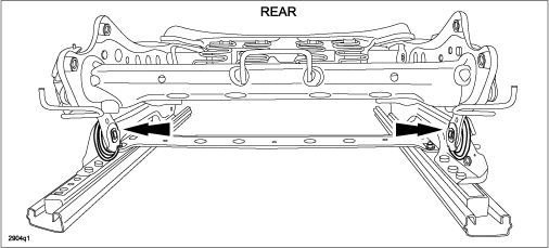
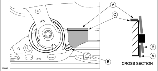
- Starting with the REAR of the seat adjuster unit (as shown below), attach a piece of masking tape onto the inner sides of the left and right sliders to avoid scratch damage during the repair.
NOTE: Attach the masking tape (A) under the balance spring hook (B) and over the top of the slider (C).
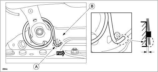
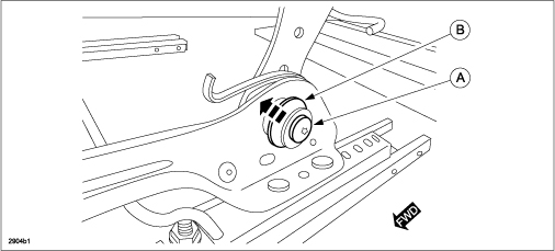
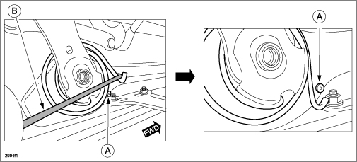
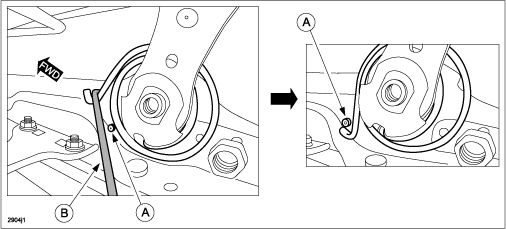
- Using a flat-blade screwdriver with masking tape on the tip, gently pry the balance spring hook (A) away from the slider surface (B).
WARNING: Be careful not to pinch your fingers.
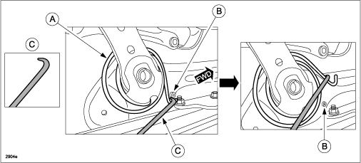
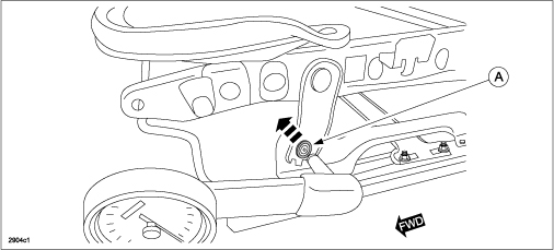
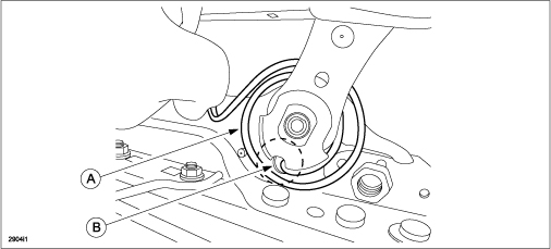
- Release the rear balance spring (A) hook from the pin (B) using a tool with a hooked end (C) (as shown below) or with needle-nose pliers.
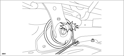
WARNING: The balance spring may jump out suddenly during removal, so keep your hands and face away from the balance spring to avoid injury.
- Repeat Steps 5 – 6 on the opposite side rear balance spring.
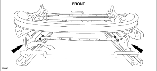
- Remove four (4) Torx T30 bolts that secure each link (A).
- Move to the FRONT of the seat adjuster unit.
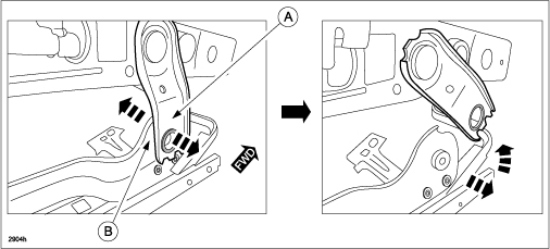
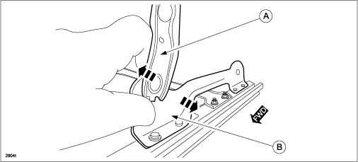
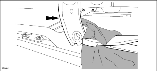
- Detach the inner link (A) from the slider (B) by gently bending the slider outward and the link inward.
CAUTION: DO NOT bend the slider too much as it may become deformed and cause improper operation.
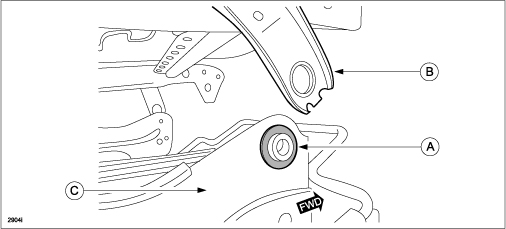
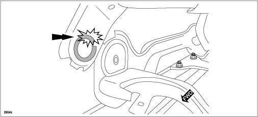
NOTE: Depending on specific production date of the vehicle, some CX-5 models may have plastic washers (A) installed between the front link (B) and the slider (C). ALWAYS BE SURE TO RE-USE THE PLASTIC WASHERS when installing the new seat adjuster lift unit.
- Repeat Step 10 to detach the opposite side inner link from the slider.
- Move back to the REAR of the seat adjuster unit.
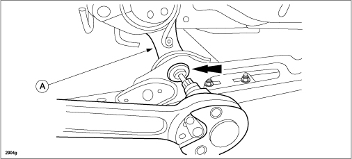
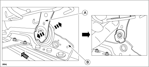
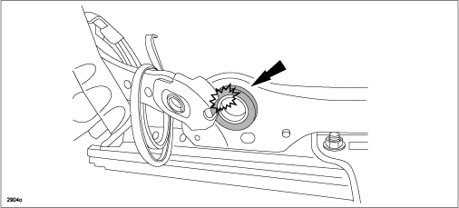
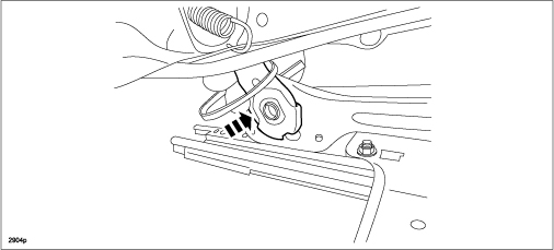
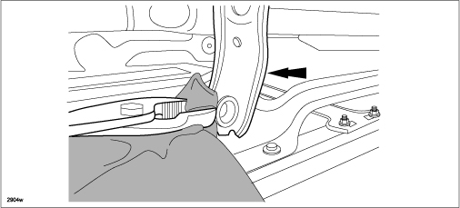
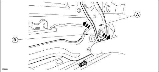
- Detach the inner link (A) from the slider (B) by gently bending the slider outward and the link inward.
CAUTION: DO NOT bend the slider too much as it may become deformed and cause improper operation.
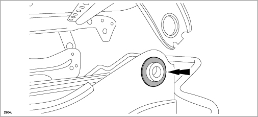
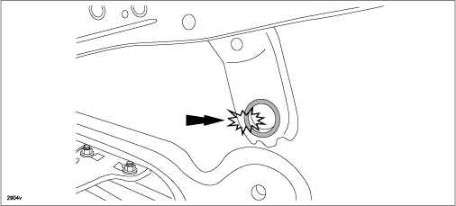
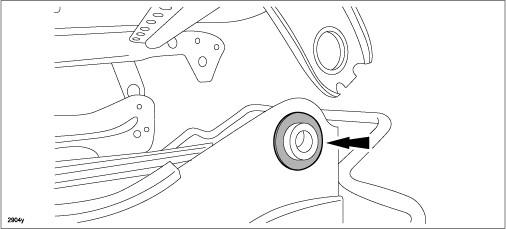
CAUTION: DO NOT damage the bushing during link removal.
- Repeat Step 13 to detach the opposite side inner link from the slider.
- Proceed to “DRIVER SEAT ADJUSTER UNIT ASSEMBLY”.
DRIVER SEAT ADJUSTER UNIT ASSEMBLY:
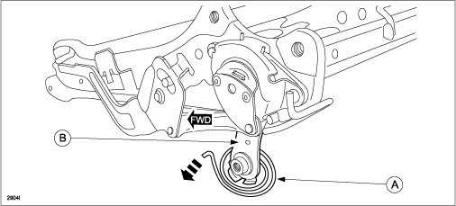
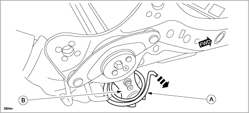
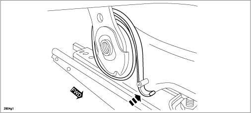
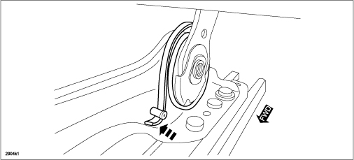
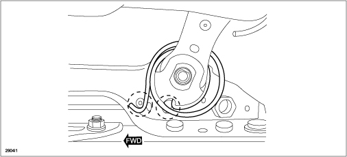
- Working from the REAR of the seat adjuster unit, place the new rear balance springs (A) around the left and right seat adjuster unit links (B).
NOTE: IT IS VERY IMPORTANT TO CORRECTLY POSITION THE NEW REAR BALANCE SPRINGS around the rear seat adjuster unit links before assembly.
NOTE: The end of each balance spring must be facing outward (as shown below). LEFT REAR:
RIGHT REAR:
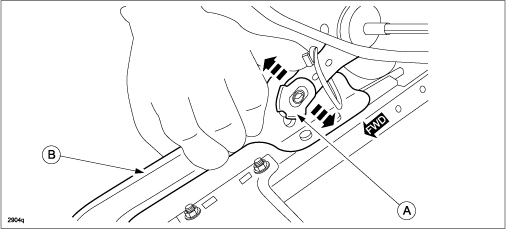
- Rear-Outer: Install the link (A) onto the slider (B).
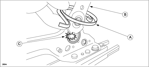
CAUTION: DO NOT damage the bushing during link installation.
- Push the link into proper position.
- Rear-Inner: Install the link (A) onto the slider (B) while bending the slider outward and the link inward.
CAUTION: DO NOT bend the slider too much as it may become deformed and cause improper operation.
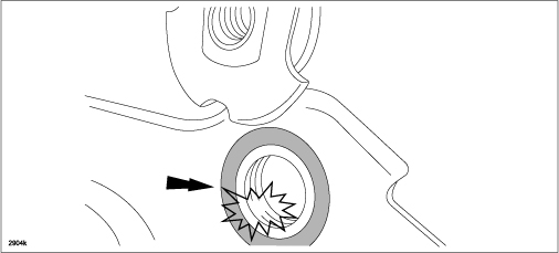
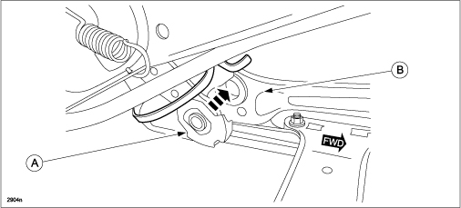
NOTE: Verify that the rear balance spring (A) has been properly positioned around the link (B).
CAUTION: DO NOT damage the bushing during link installation.
- Push the link into proper position.
- Front-Outer: Install the link (A) to the slider (B) while bending the slider inward and the link outward.
CAUTION: DO NOT bend the slider too much as it may become deformed and cause improper operation.
NOTE: Be sure to re-install the plastic washer if originally installed.
CAUTION: DO NOT damage the bushing during link installation.
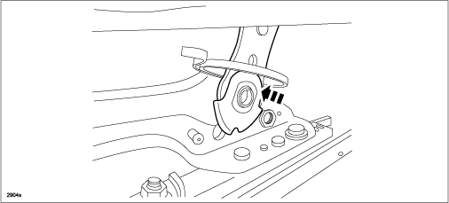
- Front-Inner: Install the link (A) to the slider (B) while bending the slider inward and the link outward.
CAUTION: DO NOT bend the slider too much as it may become deformed and cause improper operation.
NOTE: Be sure to re-install the plastic washer if originally installed.
CAUTION: DO NOT damage the bushing during link installation.
- Tighten four (4) Torx T30 bolts to the specified torque.
Tightening Torque: (15.7 – 22.6 Nm)
REAR: Tighten bolt (A) with washer (B).
FRONT: Tighten bolt (A) without washer.
NOTE:
- DO NOT pinch the spring between the link and slider while tightening the bolts.
- Verify that the spring moves freely after all the bolts have been tightened.
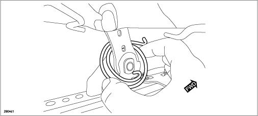
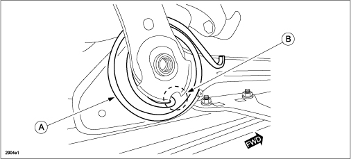
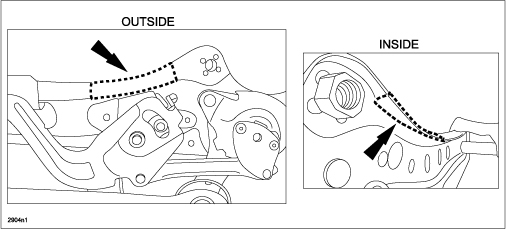
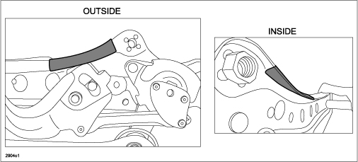
- OUTER-SIDE: Install the balance spring (A) by hooking the end of the spring into the opening (B).
- Hook the other end of the balance spring around the pin (A) using the hook tool (B) or with needle-nose pliers.
- Remove the masking tape from the slider.
- Push the end of the balance spring inward until it contacts the slider.
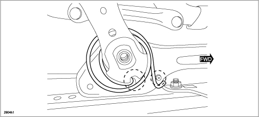
- Verify that both ends of the balance spring are securely hooked into position.
- INNER-SIDE: Install the balance spring (A) by hooking the end of the spring into the opening (B).
- Hook the other end of the balance spring around the pin (A) using the hook tool (B) or with needle-nose pliers.
- Remove the masking tape from the slider.
- Push the end of the balance spring inward until it contacts the slider.
- Verify that both ends of the balance spring are securely hooked into position.
- After degreasing the upper seat frame area, attach the piece of black tape (from kit) as shown below.
NOTE: When looking from the space between the seat cushion and the cover, the silver color of the seat lift frame is visible. By attaching the black tape to the upper frame, the silver color is covered up.
- Install the front seat adjuster unit according to the instructions on MS3 online or the Workshop Manual (section 09-13).
- Replace the front seat side cover clip, recliner knob (with lever type recliner knob) and the lifter knob with new parts.
PART(S) INFORMATION
| MAZDA6 | |||
| Part Number | Description | Qty. | Notes |
| GHY2-88-H50 | Driver Seat Adjuster Unit (LH)* | 1 | Replaces part GHK2-88-H50* |
| KF61-88-1H5 -02 | Recliner knob (with lever type recliner knob) (LH) | 1 | Replacement Parts |
| GHK2-88-28X -02 | Lifter knob (LH) | 1 | |
| KD45-88-585 | Front seat side cover clip | 2 | |
| CX-5 | |||
| Part Number | Description | Qty. | Notes |
| KFY0-88-H50 | Driver Seat Adjuster Unit (LH)* | 1 | Replaces part KF49-88-H50* |
| KDY6-88-H50 | Driver Seat Adjuster Unit (LH)* | 1 | Replaces parts KD33-88-H50*
and KD45-88-H50* |
| KF61-88-1H5 -02 | Recliner knob (with lever type recliner knob) (LH) | 1 | Replacement Parts |
| KD45-88-857 -02 | Lifter knob (LH) | 1 | |
| KD45-88-585 | Front seat side cover clip | 2 | |
* The driver seat adjuster unit parts listed in the table above are specific to the customer complaint (Driver Seat Gradually Moves Down By Itself) outlined in this document. When replacing the seat for any other reason, use the EPC to determine the correct seat part number(s).
